 welcome
bien venido
welcome
bien venido
kenwood mods page 73s
W7AGR
proceed at your own risk
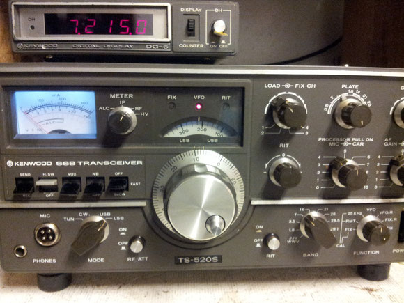
my kenwood ts520 modified the cool blue
ligth
 here is the instructions how to access to the second menu aka (service menu).......
I did manage to find some very useful information regarding the SERVICE MODE for the TS-590S. The service mode menu was borrowed from
the TS-570S. The 570 used the plug I show here and ribbon cable that is used to separate the radio chassis. Since you won't be doing that, I suggest you make up the connector from the pack of
plugs you received with your 590. The jumper is from PIN8 ~ PIN 9. These two pins should be shorted together. Now simply plug the connector into the ACC2 din slot and prepare to turn "on" the
radio. With two fingers, push the [MIC] and the [NR] buttons
while you turn on the radio. The number MENU "88" should appear in the "memory" position on the main screen. When the number
appears, you may remove the adjustment jig (I do not). Now select the adjustment Menu Mode using the [MULTI/CH] knob. You
may change any adjustment data, but keep in mind it will not be active till you write the data and press the [CLR] to enter the
VFO mode.
Changing the data is done using the [M.IN] button or the [SCAN] button. You may also use the "hand mic" [UP] or [DN] keys. This sometimes makes things a bit easier, but the buttons on the face of the radio work just as well. To write your adjustments, you
simply scroll to MENU "60" and use the [MIC] key as explained above,
to (good) the changes. To cancel the adjustment menu, hit the [CLR] key. If you turn off the radio the "write" mode is also
cancelled, so you really don't have much to worry about. However keep in mind that you should keep a cheat sheet. That way you will know if your adjustments helped or hindered the radio
operation. There is a PDF file that will help explain the menu.
Note: that with the jumper in place you cannot transmit, so "turn off the radio" and remove the plug. Now turn the radio "ON".
There is also an XLS file that goes into the menu as well. I will try to find that file and place it on the site for your review. Never-the-less, if you want to play with the radio
service menu, the information I gathered here will be helpful.
One thing to note...after you enter new data and set [CLR] to write the information you will receive a "good" for
your effort. I mean the menu will read as "good", like "good job" or "good for you" or "good luck". You make the call because I fear that you may be playing with fire. Always keep
notes...
warning: not recommended to change
anything else if you know what are you doing other wise you put your rig out of service with any mistake................73s
Go To the Kenwood DG1 mods page
Go To the Kenwood DG5 mods page
Go To the Kenwood General mods page
Go To the Kenwood MC45 mods page
Go To the Kenwood MC46 mods page
Go To the Kenwood MC50 mods page
Go To the Kenwood MC85 mods page
Go To the Kenwood PS50 mods page
Go To the Kenwood QR666 mods page
Go To the Kenwood R1000 mods page
Go To the Kenwood R5000 mods page
Go To the Kenwood R599 mods page
Go To the Kenwood RC1A mods page
Go To the Kenwood T599 mods page
Go To the Kenwood TH205 mods page
Go To the Kenwood TH215 mods page
Go To the Kenwood TH22 mods page
Go To the Kenwood TH225 mods page
Go To the Kenwood TH25 mods page
Go To the Kenwood TH26 mods page
Go To the Kenwood TH2600 mods page
Go To the Kenwood TH27 mods page
Go To the Kenwood TH28 mods page
Go To the Kenwood TH45 mods page
Go To the Kenwood TH47 mods page
Go To the Kenwood TH48 mods page
Go To the Kenwood TH75 mods page
Go To the Kenwood TH77 mods page
Go To the Kenwood TH78 mods page
Go To the Kenwood TH79 mods page
Go To the Kenwood THD7A mods page
Go To the Kenwood THD7E mods page
Go To the Kenwood TM201 mods page
Go To the Kenwood TM211 mods page
Go To the Kenwood TM221 mods page
Go To the Kenwood TM231 mods page
Go To the Kenwood TM241 mods page
Go To the Kenwood TM251 mods page
Go To the Kenwood TM255 mods page
Go To the Kenwood TM321 mods page
Go To the Kenwood TM411 mods page
Go To the Kenwood TM431 mods page
Go To the Kenwood TM451 mods page
Go To the Kenwood TM531 mods page
Go To the Kenwood TM621 mods page
Go To the Kenwood TM701 mods page
Go To the Kenwood TM702 mods page
Go To the Kenwood TM721 mods page
Go To the Kenwood TM731 mods page
Go To the Kenwood TM732 mods page
Go To the Kenwood TM733 mods page
Go To the Kenwood TM741 mods page
Go To the Kenwood TM742 mods page
Go To the Kenwood TM941 mods page
Go To the Kenwood TM942 mods page
Go To the Kenwood TM2530 mods page
Go To the Kenwood TM2550 mods page
Go To the Kenwood TM2570 mods page
Go To the Kenwood TMD700 mods page
Go To the Kenwood TMG707 mods page
Go To the Kenwood TMV7A mods page
Go To the Kenwood TR751 mods page
Go To the Kenwood TR2200 mods page
Go To the Kenwood TR2400 mods page
Go To the Kenwood TR2500 mods page
Go To the Kenwood TR2600 mods page
Go To the Kenwood TR3500 mods page
Go To the Kenwood TR7200 mods page
Go To the Kenwood TR7400 mods page
Go To the Kenwood TR7600 mods page
Go To the Kenwood TR7330 mods page
Go To the Kenwood TR7800 mods page
Go To the Kenwood TR7850 mods page
Go To the Kenwood TR7900 mods page
Go To the Kenwood TR7930 mods page
Go To the Kenwood TR7950 mods page
Go To the Kenwood TR8300 mods page
Go To the Kenwood TR9130 mods page
Go To the Kenwood TR9250 mods page
Go To the Kenwood TR9350 mods page
Go To the Kenwood TS50 mods page
Go To the Kenwood TS120 mods page
Go To the Kenwood TS140 mods page
Go To the Kenwood TS180 mods page
Go To the Kenwood TS430 mods page
Go To the Kenwood TS440 mods page
Go To the Kenwood TS450 mods page
Go To the Kenwood TS520 mods page
Go To the Kenwood TS530 mods page
Go To the Kenwood TS570 mods page
Go To the Kenwood TS680 mods page
Go To the Kenwood TS690 mods page
Go To the Kenwood TS700 mods page
Go To the Kenwood TS711 mods page
Go To the Kenwood TS770 mods page
Go To the Kenwood TS790 mods page
Go To the Kenwood TS811 mods page
Go To the Kenwood TS820 mods page
Go To the Kenwood TS830 mods page
Go To the Kenwood TS850 mods page
Go To the Kenwood TS870 mods page
Go To the Kenwood TS930 mods page
Go To the Kenwood TS940 mods page
Go To the Kenwood TS940 Assembly Error Corrections
Go To the Kenwood TS950 mods page
Go To the Kenwood TS2000 mods page
Go To the Kenwood TS2400 mods page
Go To the Kenwood TW4000 mods page
Go To the Kenwood TW4100 mods page
Problem with the memories
I bought last year a Kenwood TS-570D HF transceiver. After a few months of good working i got a problem : Everytime if i switch off the power i lost all the memories, including the value
for the IF filter bandwidth (menu item 46) which is normally held even if you reset the transceiver! I thought immediately on a battery problem. It was, but there was more. I got garanty to this
transceiver so i brought it away for a repair. They tell me it was a known problem by Kenwood that "a reset IC" was causing this trouble. They replaced a battery and an IC. Remember this if you
got problems with your transceiver !
Kenwood TS-570D MARS/CAP Modification
This modification is provided "as is".
It is illegal to operate outside the limits of your class license or permits.
- Disconnect the power cord and antenna coax from the transceiver.
- Remove the top and bottom covers.
- Remove the top screw from each side of the front panel assembly.
- Loosen the bottom screw from each side of the front panel assembly.
- Carefully rotate the front panel forward to gain access to the Control board (X53-3690-10).
This board is mounted vertically against the body of the transceiver. It is not the board that is mounted in the front panel assembly. - Locate and remove the chip resistor R41 from the Control board.
- Assemble the transceiver then perform the CPU reset procedure by holding the A=B button depressed as power is turned on.
TS-570 Batteries
It seems incredible, but there is a lithium battery in the Kenwood TS570 that apparently lasts about 6 months. Replacing it is a major trip into the innards of your radio.
Clif of (a Kenwood Service center) was kind enough to tell me what to do, and I thought I would write up his instructions and my experience in case someone else needs it.
According to Clif, the microprocessor must reset correctly or the battery will drain quickly. Therefore you must follow these instructions, as odd as they seem.
Before you begin, you need the radio on a nonconductive surface, a phillips screwdriver and a CR2032 battery (Radio Shack has them). You also need the radio's power supply hooked up.
- Have the radio hooked up to 12V. Turn the radio off but leave the supply on.
- Remove the four screws from the top of the case.
- Then remove the 4 screws on the side and lift the top free.
- Turn the radio over and remove the 4 screws from the bottom that holds the entire case on. Don't bother with the service panel.
- Turn the radio right side up and notice there are 4 screws (2 on each side) that hold the front panel on. Two of these are in slots, and two are in holes. Remove all 4 screws. BE CAREFUL. The panel is attached with several cables and yanking them loose is probably not a good idea.
- Carefully separate the panel from the radio chassis. Note the battery in the little holder. The + side of the battery is facing out.
- The battery holder is spring-loaded; you don't need to open it. Just gently push the battery and slide it upwards, freeing it of the holder and replace it with the new battery (remember + faces you).
- Reseat the panel, lining up the screw holes and replace the screws.
- If you want, at this point, turn the radio on and off again.
- Replace the covers. Remember, don't put the side screws in until the top and bottom are in place.
That's it! According to Clif the problem won't reoccur. We'll see! Just be careful when you attempt this. Lots of things can go wrong. The case is very tight fitting, so don't drop the pieces and bend them out of shape or you will be sorry. Good luck!
UPDATE
As of March 29th, my battery failed again (yep, about 6 months). I have a month left on my warantee, so I'm planning on trying to get something resolved. I'll post here about what I find out.
Kenwood did in fact take the Radio back and apparently installed a diode at no charge. With any luck, this will fix the problem.
Kenwood TS-570DG MARS/CAP Modification
This is for the DG model only!
- Disconnect the power cord and antenna coax from the transceiver.
- Remove the top and bottom covers.
- Remove the top screw from each side of the front panel assembly.
- Loosen the bottom screw from each side of the front panel assembly.
- Carefully rotate the front panel forward to gain access to the Control board (X53-3690-10). This board is mounted vertically against the body of the transceiver. It is not the board that is
mounted in the front panel assembly.
- Remove the square cover with 4 screws on it. LOCATE IC 5 go to the lowest point by ic 5 there are 2 resistors between the is 5 chip and the screw hole REMOVE the HORIZONTAL ONE
- Assemble the transceiver then perform the CPU reset procedure by holding the A=B button depressed as power is turned on.
You will now have all the other frequencys you couldent transmit on now...
kenwood ts 850 mods
KENWOOD TS-850:
MODIFICATION FOR EXTERNAL KEYING,
WHILE USING THE INTERNAL KEYER
BY: N7EX (ex-N0DH), Dave Henderson
One of the minor draw backs to the TS-850 as a CW contest machine is the inability to use the internal keyer in conjunction with an external keying circuit such as a personal computer or auxiliary memory keyer. As designed you must manually throw a switch from internal to external keying to switch between one or the other. To make matters even more inconvenient this switch is on the back of the unit and is not readily accessible during normal operation.
Simply said this modification involves running a new keying line from the junction of S1 and D51 on the IF Board. For convenience this additional keying line can be wired to the DSP1 and/or DSP2 RCA phono jacks if you do not use the external DSP unit.
The modification to the unit to resolve this problem takes less than 30 minutes to accomplish and can be done without "permanently" modifying the unit which would detract from its future resale value. If you don't use the external DSP unit then the two RCA phono jacks marked DSP1 and DSP2 can be used as additional keying input jacks as will be outlined below. If you use the external DSP unit then the modification can still be accomplished by running the external keying line out on a "pigtail." I highly recommend the purchase of a service manual which will greatly improve your ability to indentify the circuit points involved in the modification. Considering that the radio costs $1500 what's another $30 to keep from messing it up! By the way compared to the two TS-930's that I nursed through the 80's, this radio is a breeze to trouble shoot and repair which I have had to do twice through no fault of Kenwood (long stupid story ~8>).
From here you proceed at your own risk, if you fry the radio DON'T CALL ME. A precision low wattage solder pencil for doing surface mount soldering is recommended, If all you have is a 150 watt Weller solder gun then read no farther your better off taking the unit to an expert rather than "melt" the circuit traces.
I assume no risk for the accuracy or completeness of the enclosed information. All yee who enter here embrace all hope for you may likely have a better contest radio when you are done.
1) Turn the unit upside down with the back of the TS-850 toward you.
2) Remove the bottom cover.
3) In this position the IF board is on your left.
4) Remove all the screws holding the IF board to the chassis.
(put them in a jar or something for safe keeping).
5) Unplug enough of the cabling to allow you to tilt the board up so that you can access the bottom side of the board underneath S1 the "External/Internal" keying switch.
6) On the bottom side of the board directly underneath S1 you will see 6 solder pads arranged in two rows of three pads each.
7) The middle pad on S1 nearest the back of the radio should be GROUND, solder the braid of an approximately 9 inch piece of small audio style shielded cable to this point, being careful to dress
the coax so as not to short to other circuitry.
8) The middle pad on S1 in the next row up of three pads is the keying line. Solder the center of the shielded cable to this point.
9) Route the other end of the shielded audio cable through the chassis in the vicinity of the DSP jacks above.
10) Carefully inspect all solder joints for shorts, etc. Replug the wire harnesses unplugged in step 5 above and reassemble the board to housing. Reassemble the bottom cover.
11) Turn the unit over and remove the top cover.
12) Find the DSP input board with the three RCA phono jacks on it at the rear of the unit. The two DSP jacks are on the right when facing the rear of the unit. There are two connectors on this
board (a 2pin and a 4pin). Unplug the 4 pin connector. Obtain another 4 pin connector and connect as follows (or directly solder to the underside of the board as follows) If you only need one
additional CW jack then ground is pin 2 (closer to center of the radio)connect the braid of your new key line to this pin. The input from the middle RCA phono plug is pin 1 connect the ceneter
conductor to this pin. Like wise if you want two additional CW jacks then do as above plus add a short between pins 1 and 3. If you want a small RF choke or some ferrite beads on the center
conductor of the audio cable may prevent keying problems in high RF field environments...
14) Close the unit up and switch S1 to INTERNAL keying. You should now be able to key the unit via the internal keyer (Via the standard key input jack) or with an external keyer or computer via
the old DSP jacks, without having to switch S1.
TS-850 Separate Receive Antenna Modification #1.
This modification was developed by Brian, WA3WJD
Make a short loop of white telfon cable with a male and female BNC connector.
Loop it out of the back of the rig so just enough of the coax sticks out so the BNCs can be joined with a barrel connector.
Locate the little header connector on the filter board in the TS-850 that is on the receiver side of the TS850 antenna relay. Pull that connector loose.
Spend a little time tracking down male and female header connectors that match what Kenwood uses. Install those on the ends of the white teflon coaxes sticking in the back of the radio.
For normal use, just connect the BNCs with a barrel connector and the rig is normal. For Beverage use, connect an extra antenna switch common and ant #1 to the BNC connectors, and put ur
Beverages on the other positions.
TS-850 Separate RX antenna input mod #2.
This is near the top of everyone's list when they are asked "What things bug you about the TS-850S." I initially overcame this deficiency by modifying my amplifier so I could connect a different receive antenna to the TR relay. However, I wanted to change things so there wasn't as much RF getting into the RX antenna due to close proximity to the amplifier's output. This became a problem when using the same receive antenna on a second radio (you knew two radio contest operating was going to work its way in here somehow).
Ville, OH2MM had provided me with instruction on how he modified his TS-850S to have a separate RX input and this inspired me to try it.
Here are some simple steps to hopefully inspire others:
It took me an unrushed two hours to do all this.
1. Remove the top panel (you don't need to take off the bottom one).
2. Remove the plate which sits between the fan and the back of the radio. This covers the output filter PC board.
3. Unsolder the connections to the SO-239 output connector.
4. Remove the three cables from the PC board next to the SO-239. This includes two coax and one 3 conductor harness.
5. Remove the two screws holding in the PC board and remove it.
6. Locate the trace that goes from the relay's normally closed contact. You can use an ohm-meter to find it - probe from the wire that went to the SO-239. You will find a short trace on the back
of the board which runs to a chip capacitor. Cut this trace and solder some very small coax to each side of the cut - connect ground to the nearby ground trace.
Make the cables about 4 inches long.
7. Remove the antenna tuner. There are 2 screws in the back and front (you will need a magnetic screw-driver) and one on the side. You will need to carefully unplug two wire harnesses and one
coax connector.
8. Drill two holes for phono jacks on the back of the radio. Be careful not to obstruct the screw hole for one of the screws in the back of the antenna tuner. The best place is between the RF
output connector and the groundpost. Put them on top of each other and as close to the bump on the back panel as possible. I used a vacuum cleaner while drilling to make sure no metal chips went
anywhere.
9. You will find a small hole under the SO-239 where you can feed the two coaxs through. Solder them to the phono jacks and reassemble everything. I put back to back diodes on the RX antennas
input, but you may not want to do this. A better thing would be to add a relay to disconnect the RX antenna input when transmitting. I took care of that in project #2.
10. Obviously, you will need a jumper cable to make your receiver work again.
PROJECT #2 - The switch box:
- Parts list:
- 4 position rotary switch
- DPDT 12 VDC relay
- 1 K Ohm pot (optional)
- 12 phono jacks (or you can get by with 9)
- mini box for above and knobs.
- Clamp diode for relay coil if not included in relay
This box does two things: disconnects the receive antenna input when transmitting and allows selection of the transmitting antenna or one of three RX antennas when receiving. The pot can be used for RF attenuation if your rig doesn't have one.
The relay gets controlled by the PTT output from your rig that normally would go to your amplifier. Then one set of the contacts is used to key your amplifier. Don't forget to put a diode across the coil of your relay if there isn't one internally. Otherwise, you will have undesired arcing across the contacts of the relay in your radio.
The other set of contacts disconnect the output of the rotary swtich when transmitting. The rotary switch selects either the signal coming from the transmitting antenna (from the TR relay in your rig) or one of three receiving antennas. I use two phono jacks per RX antenna so I can feed them to other boxes for other radios. I also use two jacks for +12 volts so I can jumper power to another box.
You can build up one of these boxes in an hour or two. You can epoxy the relay to the mini box.
If you want the pot there to act as an attenuator, I just hook it up like you would a volume control: one end is ground, the other end goes to the output of the rotary switch and the wiper goes to the output. Use shielded cable as much as possible to avoid stray pickup.
Computer Interface for the TS-850, without using the IF-232 Level Converter.
Mod developed by N6TR, and possibly others, with zener idea added by K6LL.
Note: This interface will work with "TR," contest logging software by N6TR.
Computer Interface:

                    470 ohms
DB9 PIN 3 (TXD)  ----////------------ TS850 ACC 1 PIN 3 (RXD)
(DB25 PIN 2)                  |
                              |
                              |
                            ----  5 VOLT ZENER DIODE
                              /
                             /
                              |
                              |
DB9 PIN 5 (GND)  ------------------------  TS850 ACC 1 PIN 1 (GND)
(DB25 PIN 7)

DB9 PIN 2 (RXD)  ------------------------  TS850 ACC 1 PIN 2 (TXD)
(DB25 PIN 3)

                                   -----  TS850 ACC 1 PIN 4 (CTS)
                                   |
                                   |
                                   |
                                   -----  TS850 ACC 1 PIN 5 (RTS)
TS-850 Power Output Control
VR7 on the RF Board (bottom side of radio). 125 watts or so on cw is safe. Do not exceed
100 watts on SSB, since distortion will broaden the transmitted signal.
TS-850 Level Attenuator for DRU-2 playback audio.
1. Remove the little hatch on the top of the radio.
2. With the front of the radio facing you, find connector CN505. It is a five pin connector near the filter DIP switches. The white wire on the leftmost terminal carries the DRU audio
output.
3. Cut the white wire and insert a 100K ohm micromini pot, shunted with a 220 pf capacitor. Adjust the pot until DRU playback level matches live microphone level.
TS-850S All band transmit
Kenwood markets this radio worldwide, and has made oro visions to allow the radio to transmit between 1.625 mhz and 29.999 mhz.
I am providing this modification for INFORMATIONAL PURPOSES ONLY! DO NOT TRANSMIT OUT OF BAND, THIS WILL JEAPORDIZE YOUR LICENSE, AND HAVE THE FCC, AND/OR INTERNATIONÁL AUTHORITIES KNOCKING AT
YOUR DOOR!!!
The All-band transmit modificatéon requires the removal and re- location of a diode on the the digital board which is located behind the front panel. The US version of the radio has diode D11
installed, and diode D9 removed. D11 must be removed, and installed in the D9 position. This modification IS NOT for the faint of heart, as it entails removing the front panel, and the digital
board. Note that the digitál board has solder holes thát are through-soldered; that is, there are circuit traces on both sides of the board, so make sure that ALL solder is removed from the
holes. This modification will also allow the antenna tuner to tune anywhere the receiver is tuned. This modification should ONLY be performed ây those familiar with soldering and de-soldering
techniques, and requires patience, and dexterity.
kenwood
ts 520 mods
11 meter mods: just take a number down from 1 of the 10 meter
crystals example: if number is 39.995 go to 38.995 you lose 10 meter
or can add an spdt switch note: its illegal to transmit out of the
band, not responsible for missuse or damage to your equipment proseed at you own risk >>>>>>>73s
In the TS-520SE, the heater switch has been replaced with a CW WIDE/NARROW select switch. For those operators who desire this type feture for their transceiver, the following information may be
considered as a guideline.
TS-520S series transceivers
- A minature SPDT switch may be installed at the operators preference, on the rear side, or bottom panel. Use this to switch the CW or SSB filters by wiring the BROWN lead, which normally is transferred to the CW terminal on the IF unit, between the SSB filter, for WIDE , and CW for NARROW.
- A Traditional solution has been to use the FIX CH switch, position 3 and 4 for filter switching. This may be donw by completely rewireing the switch, or by leaving the switch wiring and the
filter wiring as for normal operation, and bridging the following terminals:
     A.   FIX CH C terminal to IF SSB Terminal
     B.   FIX CH 4 terminal to IF CW terminal
          Placing the FIX CH switch to 4 will operate the SSB filter
                  in CW mode.
TS-820S Series Transceivers
- Similar to the TS-520 series, a miniature SPDT toggle switch may be installed at the operators preference a the rear or on the obttom cover.
- The FIX CH switch, or Digital Hold switch may be rewired to control the CW wide/narrow function
On the MODE switch, S6-1, the SSB filter control is GREEN, and the CW filter control line is GREY. Break the GREY line and connect it from the MODE switch to the SPDT common terminal. Connect the
GREY line to the IF unit ot one terminal, and bridge tht GREEN SSB line to the other Switch terminal.
DG-5 Standard Service Procedure
(Supplement to the DG-5 Service Manual)
Introduction
A majority of DG-1 failures are caused by nothing more than an intermittent opening of a plated-through hole connecting top and bottom foil paths of the PC board.
Before any component level service is attempted, it is advisable to eliminate the possibility of an intermittent connection causing or complicating counter failure.
Procedure:
- Disconnect all cables.
- Remove cabinet: 2 screws at the rear, 2 screws with star washers on the bottom.
- Disassemble display from chassis; 4 countersunk screws on the side rals.
- The display unit has 2 through holes without leads, and the Counter main board has 82 through holes without leads passing through them. Ideal service would be to first remove all solder from these holdes using vacuum desoldering devices, or WIK-IT braid. Then, pass a length of #24 tinned bare wire into each clean through hole, solder, and clip flush. For 10 holes listed under IC's solder sparingly so as not to create a solder bridge under the component. For the remaining 72 holes, inspect each "pinned" connection from both sides to ensure (1) no bridge and (2) a good solder joint.
- Wash the display to counter Board PC board connectors (male and female) with FRESH trichlorethelyne. Heat dry and inspect for flux residue. Spray the connectorrs with silicone.
- Similarly, clean and coat the rear panel RCA jacks as in step 5.
- Reassemble, reversing steps 3,2,1.
How to solder on the DG-5 pc board.
- Use a low power pencil iron of 35 watts or less.
- Use rosin core solder, small diameter.
- Do Not create solder bridges or splotches.
- Do Not overheat or otherwise lift the foil from the board.
- Wash excess flux away with FRESH trichlor, and a small flux brush.
Neatness counts - it's your radio.
Through Hole Accounting
Display unit - 2
Counter unit -82
Total -84
Locations:
A.   Under; IC2,4,13,20-25,34,  1 each
     Total 10

B.   Adjacent or between; IC3,13-14,15-16,22-23 1 1 each
                          IC1-2,6,18              2 each
                          IC12                    3 each
     Total 13

C.   Located between rows: IC13-18,20-25  - 5
                           20-25, 26-31   - 10
                           IC26-31, 32-37 - 15
                           IC32-37, 38-39 - 25
     Total 55

D.   At rear panel: FS7805 regulator - 1
                    2SD235 transistor- 3
     Total 4

E.   Display unit - 2
Additional Points
- R126 &129 are power resistors located at the left rear corner of the PCB. Remove the tubing from their outside legs and resolder each lead to the top foil path. Specific symptom for this
failure is no display, and no decimals.
- For counters which roll, random count, or inject hash noise back into the TS-520/520S especially when hot, install an additional .1uF @ 12v bypass cap across the FS7805 regulator on the foil
side of the PCB from the center ground lead to the outside leg, across C89.
- For complaints of hum or digital noise from the DG-5 back into the TS- 520/s both during RX and TX, tighten the mounting screws which supply ground to the Carrier unit X50-0009-01 in the transceiver.
Please annotate your service manual.
Service notes on TS-520
Author: Trio-Kenwood Communication, inc.
Transmitter
- No switching of final relay: Bad Q8 on X54-0001-00 2SA562Y.
- No drive: C3 100pf in final box is cold soldered.
- Low output: Check the plate load cap for touching plates.
- 3.5 MHz low output: Replace burned 47pf 3KV at load wafer.
- No TX: Final choke burned out in final VOX L8.
- No RX or TX: Bad common amp. Q1 3SK35GR in IF unit X48-1060-00.
- No ACC: No plate current Q2 3SK41 If unit X48-1060-00.
- No TX relay: Q8 2SA562Y on VOX unit. Also R18 1K resistor relay control.
- No TX or RX: Check 9 volt terminal on FIX AVR (X43-1100-00) is loose.
- No CW TX: Bad 9 volt regulator. Check D3 WZ061 on X43-1100-00.
- No TX: Solder touch between TIF and key terminal on X44-1080-00.
- No drive to TX: Check RL1 on GEN unit, small reed relay (X52-0010- 01).
- No ALC meter action on 10 meters: This is normal for TS-520.
- CW chirp: Q4 2SA606L on Fix channel AVR X43-1100-00.
- ALC meter to maximum when TX: RFI terminal at X44-1080-00 is not soldered.
- No TX output: 82pf 3KV in final is burned.
- No TX output: Q3 on RF unit 3SK41 X44-1080-00.
- No bias: 10 ohm cathode resistors burned in final VOX.
- No drive or TX output: R70-71 RF unit, R5 Rectifier unit.
- No VOX: Q8 in VOX unit X54-0001-00.
- No TX: 12BY7 is bad. Shorts and burns out. R71 and 70.
- No carrier output: Q1 on Carrier X50-0009-01.
- No drive - no screen voltage: R5 470 ohm open on rectifier X43-1090- 00.
- No drive - no ALC: Q2 3SK35Y IF unit. Q3 3SK41L RF unit.
- No RF output: C13 0.04uf at pin 1 of S2001A is bad.
- Low mic gain: Q1 2SC1000 on Gen unit.
- No TX: Misconnection of brown wire after installation of CW filter.
Receiver
- Low Sensitivity: Touching RLT and 9V at function switch.
- Receiver sensitivity: No -6v at AVR: Q8 2SC735 on X43-1100-00 is bad.
- Frequency Shift: Bad carreir Xtal 3395 on carrier unit.
- VFO drift: C6 22pf, VFO unit.
- No receive: Bad Q4, 3rd IF amp 3SK35GR on X48-1060-00.
- Receiver sensitivity and bias current jump, -6v unstable: T1 oscillator transformer for -6v is bad on X43-1100-00.
- Erratic AGC action: C11 100uf 16Von X431100-00. Fix channel AVR is bad.
- Frequency shift when warmed up: Q1 in VFO 3SK22GR.
- No RX or TX: If unit C59 touch to T12 IF transformer.
- Receiver noise: Q5 3SK35Y X44-1080-00.
- Receiver sensitivity down: NBI terminal is pulled loose. Receiver at IF board.
- No S meter reading and RF gain CCW. No meter deflection: Q3 on IF unit. Q5 on RF unit.
- VFO frequency jumped: There is loose tension inside VFO.
- VFO frequency shift: Cold solder of VFO output lead to VFO output socket.
- Blows fuse when first on: Check Q1 and Q2 DC-DC converter transistor. One is possibly shorted.
- Noise blanker inoperative: R6 4.7K resistor is broken at Q2 on X54- 1080-10.
- Loud audio squeal: Q4 3SB473 on X49-0008-01 shorted.
- Low receiver sensitivity: Diode D4 1S1587 on RF unit.
- VFO intermittant: Wire to L1 in VFO is not soldered.
- No receive: Q4 3SK35Y, Q5 3SK35GR on RF unit.
- No receive: Q9 3SK35GR on IF unit.
- Hash noise in receiver: Q3 on RF unit 3SK41.
- Blows fuse: C31 power supply is shorted, 100uf 500v. Also check associated diode D3, D4.
- No RX on all bands: WWV switch is broken or a wire is loose or not soldered.
- Receiver sensitivity: Q5 on RF amp 3SK35Y.
- Receiver sensitivity: NBO terminal on X48-1060-00 is loose.
- Low audio: Check for purple wire touch to ground at 12 pin connector in rear panel.
TS-520S -6v Supply Failure
Author: Trio-Kenwood Communication, inc.
When troubleshooting a TS-520S, check all power supply voltages, including the -6v DC supply. Symptoms such as dead, blown 2A DC fuse and now dead, low RX, no TX, or similar may occur after switching between 80 and 40M.
Cause of failure may be traced to an intermittent shorting between the 14v dc and -6 dc supplies as the band switch is rotated between 40 and 80 meters. This will weaken or destroy D8, a 6v zener
on the FIX CH AVR unit.
To prevent repeat failures, break the White lead and install a 22 K ohm 1/2 watt resistor at the bandswitch S5-6, between the -6v supply line and switch terminal. An of course replace D8 on the
FIX CH AVR unit, X43-1100-00.
New Part: 22 k ohm 1/2 W carbon resistor
Please notate your Service Manual.

TS-520/520S CW Frequency Shift
Author: Trio-Kenwood Communication, inc.
Reports of intermittent frequency shift during CW operation, on the order of a few hundred cycles, may be traced directly to the Carrier Unit.
On the Carrier unit X50-0009-01, install a ground lead of #18 tinned wire or similar, between the cases of T1 transformer and X3, the LSB XTAL.
Recheck frequencies after installing this ground lead.
Please notate your service manual.
TS-520 Increased sensitivity, Better audio and Amplitude Modulation
1. Increased sensitivity.
On the RF board, Q5 is the RF RX amp. Notice that G2 is tied to the AGC line.
Bend G2 up from the socket, solder a 10k resistor to it and connect the other end of the resistor to the 9v line on the front of the board. This will allow the FET to run wide open, and you will
have a better S/N ratio. You will gain about two S units in signal and you may want to adjust your S meter to compensate. I did this mod almost a year ago and have had no problems even with
signals that were 40db over!
2. Better audio.
note: this work good i done it myself (w7agr)
only on 520 not the s model
A few capacitors should be changed to accept a wider audio bandwidth.
These will only increase the BASS response and not the treble as it is limited by the IF filter. Change the following on the generator board;
C3 (1µF) to 10µF
C4 (4.7µF) to 47µF
C5 (1µF) to 4.7µF
C8 (.047µF) to 4.7µF
C9 (1µF) to 10µF
C11 (4.7µF) to 47µF
C10 (10µF) to 22µF
This will make the Tx audio flat. Make sure that the Local Oscilator is adjusted correctly or else you will have the bass attenuated by the IF SSB filter.
I also changed the caps on the AF board.
C14 (.47µF) to 4.7µF
C13 (.047µF) to .47µF
C1 (1µF) to 4.7µF
You will also want to use a good speaker. I have an old speaker box that got gutted.
I put in a 6x9 coaxial car speaker and it sounds great! Since the audio is limited to 4Khz anyway, don't go bonkers with tweeters. You may want to play with a few caps inside the speaker to roll
off some of the very highs which will only be transistor noise anyway.
Along with changing the caps for flat audio, I installed two jacks for audio on the back of the 520. These are RCA female jacks that are used to connect to an equalizer.
Unwrap the wire on the generator board marked MA O. This is the output of the Microphone Amplifier. Connect some microphone coax from this terminal to your RCA socket on the back of the rig
marked output. Remember to ground both ends of the cable so you won't have hum/RF problems. Now connect the other RCA socket via mic cable to the wire that you unwrapped from the MA O post.
Make up a jumper cable for those times you don't want to use the EQ.
I recommend an old Radio Shack 5 band EQ. I have no RF problems at all and I run 500w PEP with the amplifier sitting next to the Kenwood. Stay awayf from EQ's that use all IC's. I find regular
transistors are better for handling RF.
3. Amplitude Modulation
This radio can talk AM in a pinch. You will be limited to SSB reception though. That's OK if you don't mind playing with the RIT to get rid of the beat tones.
I decided it was degrading the specs when I put in a regular AM detector so I pulled it out. Here is how you make it talk.
Get a DPDT relay (12v) and connect it inline with the fixed channel selector switch, so that when you select crystal 4 the relay energizes.
Now lets take the relay in two sections. The first is connecting the ouptut of the mic amp into a matching transformer via this relay. You want it connected so that the MA O is on the wiper and
the relay NC1 is connected to the Balanced Modulator. Connect the other relay terminal NO1 to the low impedance side of the transformer. Connect the other lead of this winding to ground. So when
you select fix channel 4, the relay energizes, and disconnects the mic from the balanced modulator and connectes it through the transformer to ground.
Ok now the second part of the AM mod.
Take the HIGH impedance winding of the transformer and connect one leg to ground. Take the other leg and connect it to a 47uF cap.(neg lead) Connect the positive side of the cap to an 820 ohm
resistor.
Connect the resistor to the 9v terminal (on the RF board or most any other board) Connect the junction of the resistor/capacitor to the NO2 terminal of the relay.
Connect the wiper of the relay to S on Q3 on the RF board. I found R17 to have its exposed wire connected to S on Q3. Simply scratch the paint away on R17 and solder to the resistor.
Since this design modulates after the IF, you will have full fidelity and bandwidth of your audio. If you use an EQ, don't be excessive with the highs or you will have enemys from the splash you
create. Also, there is no limiter here. If you have access to one, install it in the EQ loop.
Have fun on 80M!!
Kenwood TS-520S for QRP
The TS-520S can be operated QRP down to a few milliwatts with simple modification. Apply negative voltage on the ALC pin of the ancillary socket.
Modification consists of a 220K Ohm pot and a 9V battery.
Negative terminal of battery in series with 220K pot to ALC pin on socket.(Pin 6)
Maximum of 34 microamps drawn so battery should last a long time.
Bob Wilder, W4RHW
TS-520S MARS Mod for 4.0-4.6MHz
After trying for several months, I have finally come across a modification for the Kenwood TS-520S that will allow this rig to be operated in the 4.0 to 4.6 MHz range in MARS operation. The
modification came originally from Jim, WB4WBL (AF MARS AFA2FN) in Tampa, Florida.

The modification consists of moving the 12.395 MHz crystal from the Band Switch to a small DPDT toggle switch mounted on the bottom of the case. An additional 12.895 MHz crystal is added to the
switch for the new range needed.
This new crystal can be obtained from International Crystal Manufacturing Company. The crystal is 20pf, wire lead type.
A short piece of RG-174 coax is used to connect the new switch with its attached crystals back to the Band Switch position from which the 12.395 MHz crystal was moved from.
Once the crystals are in place, the 3.5 MHz coils are retuned to a new center frequency of 4.100 MHz. The normal tuning of all the 3.5 MHz band coils are tuned to 3.750 MHz.
The new switch is mounted between the front of the radio and the hetrodyne oscillator board.
Jim says that he still has a TS-520 with the mod in it and it still works great after almost 20 years. He has modified several 520's over the years they all worked great.
73 Bob Wilder, W4RHW
USAF MARS AFA2HD
TS-520 Novice Operation (75 watts)
Author: Trio-Kenwood Communication, inc.
HV UNIT (X43-1100-00)

- Cut wire (See figure 1) .... red color.
- Insert 33kohm resistor in series between red wire and pin 210.
- readjust bias current to 60mA.

Figure 1 (Bottom side)
AM Broadcarst interference in TS-520
Author: Trio-Kenwood Communication, inc.
We have found a few instances of customers who live near an AM broadcast station hearing that station on the 3.5 MHz band of theire TS-520. Shown below is a filter that may be installed if this occurs.

|
|
A Suggested located for the filter is on a small terminal strip that is then mounted on a mounting screw of the RF unit. This screw is located at the front corner next to the VFO. The cable
between S-9 (WWV switch) and terminal NAT of the RF unit is removed from terminal NAT and connected to one side of the filter. A short piece of RG-174/U is then connected from the other side of
the filter to the terminal NAT. This hould prevent the AM broadcast interference.
TS-520/520S BS-5 Sweep interference
Author: Trio-Kenwood Communication, inc.
BS-5 users may report ignition-like interference on 80 & 40 M from their SM-220 with BS-5. noise will be heard between 3850-3870 KHz, and 7245-7260 KHz any time the scope is on.
The sweep signal mixes with the IF (carrier) frequency. This derived signal, or its second harmonic will usually be less than an S1 signal, unless the coax ground to the scope is opened, in which case S9 may be indicated.
On the SM-220 PCB X65-1240-00, change the BS-5 +11V DC supply point:
- Cut the foil path between connector P110 pin 6 and Connector P103 pin 2.
- Install a 1S1555 diode between Connector P110 pin 6 and Connector P103 pin 1.
New Part: 1S1555 V11-0076-05
